Gr .. _distribution_grid_library:
Distribution Grid Library
In this section we will create the same ‘Distribution Grid’ from here.
However, we will do this using using GridCal as a Python Library.
Step 0: System Overview
This tutorial shows a step by step guide on how to build distribution grid system that contains: 13 Buses, 4 Transformers, 4 Loads. The tutorial shows how to create a grid using time profiles and device templates. The tutorial also contains:
Easy drag and drop creation of components.
Transformer type creation.
Overhead lines creation.
Templates for transformers and overhead lines.
Import of profiles into the loads.
Set s power flow snapshot from the profiles.
Execution of power flow.
Execution of power flow time series.
Automatic precision adjustment.
Results visualization.
Live results visualization (grid colouring).
A video tutorial can be found here2.
Note: this tutorial was made with GridCal v 4.0.0
The system grid is supposed to look like the figure below.
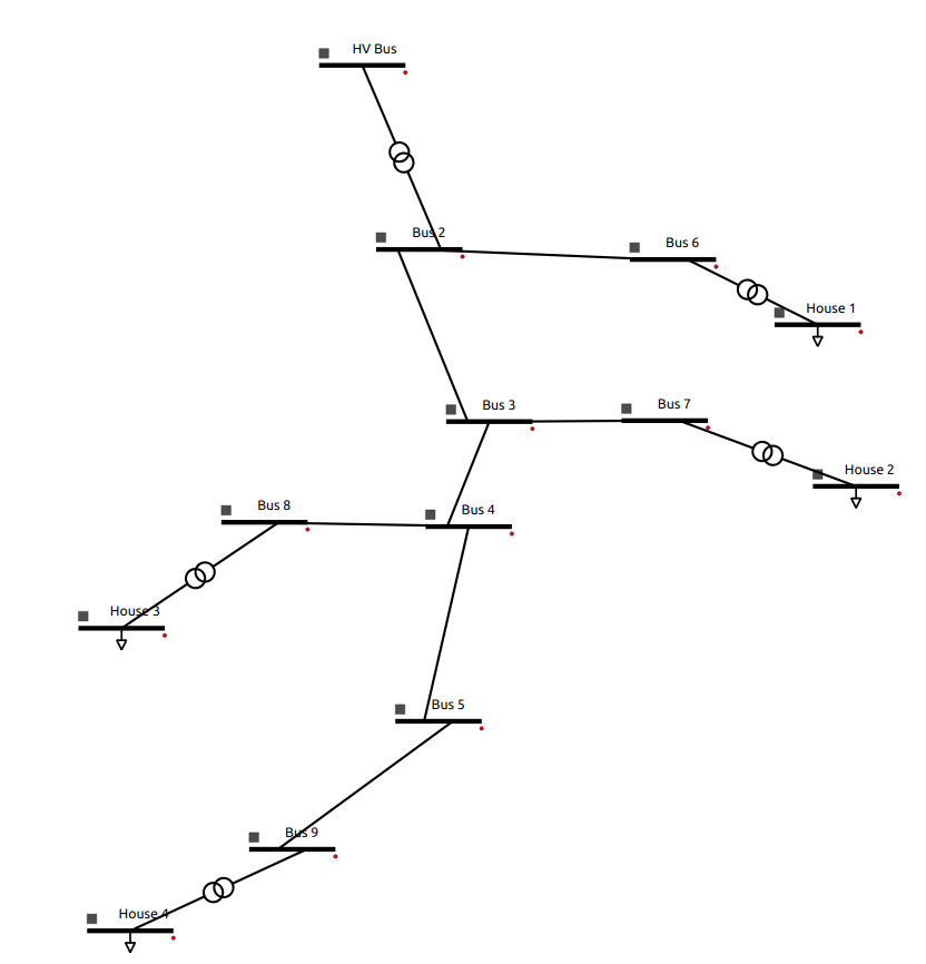
The system featurese:
9 Buses.
5 Transformers.
4 Loads.
7 Lines.
Solution file of the grid system can be found in _GitHub.
Step 0: Import GridCal and create model
Crate the grid:
from GridCal.Engine import *
grid = MultiCircuit()
Step 1: Create a Transfomer
Create two buses ‘HV Bus’ (being the slack bus) and ‘Bus 1’ with the following parameters (parameters that are omited are just default parameters):
name |
HV Bus |
Bus 1 |
Vnom[kV] |
20 |
10 |
HVBus = Bus('HV Bus', vnom=20, vmin =0.9, vmax = 1.1, r_fault = 0, x_fault = 0)
HVBus.is_slack = True
grid.add_bus(HVBus)

Bus1 = Bus('Bus 1', vnom=10, vmin =0.9, vmax = 1.1, r_fault = 0, x_fault = 0)
grid.add_bus(Bus1)
Create a transfomer ‘Transformer 1’ between the two buses:
Transformer1 = Transformer2W(bus_from=HVBus, bus_to=Bus1, name='Transformer 1', HV=20, LV=10)
grid.add_transformer2w(Transformer1)
Step 2: Create Lines of Different Lengths
Create ‘Bus 2’, ‘Bus 3’, and ‘Bus 4’:
Bus2= Bus('Bus 2', vnom=10, vmin =0.9, vmax = 1.1, r_fault = 0, x_fault = 0)
grid.add_bus(Bus2)

Bus3 = Bus('Bus 3', vnom=10, vmin =0.9, vmax = 1.1, r_fault = 0, x_fault = 0)
grid.add_bus(Bus3)

Bus4 = Bus('Bus 4', vnom=10, vmin =0.9, vmax = 1.1, r_fault = 0, x_fault = 0)
grid.add_bus(Bus1)
Creates lines between all of the buses.
‘Line 1’ between ‘Bus 1’ and ‘Bus 2’ (length 5 km.):
Line12 = Line(bus_from=Bus1, bus_to=Bus2, name='Line 12', r=1.8e-05, x=0.154323, b=0.0,rate=30, active=True, branch_type=BranchType.Line, length=5, template=BranchTemplate())
grid.add_line(Line12)
‘Line 2’ between ‘Bus 2’ and ‘Bus 3’ (length 3 km.):
Line23 = Line(bus_from=Bus2, bus_to=Bus3, name='Line 23', r=1.8e-05, x=0.154323, b=0.0,rate=30, active=True, branch_type=BranchType.Line, length=3, template=BranchTemplate())
grid.add_line(Line23)
‘Line 3’ between ‘Bus 3’ and ‘Bus 4’ (length 7 km.):
Line34 = Line(bus_from=Bus3, bus_to=Bus4, name='Line 34', r=1.8e-05, x=0.154323, b=0.0,rate=30, active=True, branch_type=BranchType.Line, length=7, template=BranchTemplate())
grid.add_line(Line34)
Step 3: Add More Lines and Buses
Step 4: Create Loads
Step 5: Create House 1 and House 2
Step 6: Defining the Main Transformer
Step 7: Defining Load Transformers
Step 8: Defining Other Transformers
Step 9: Defining Wires and Overhead Lines
Step 10: Importing Load Profiles
Step 11: Save File
To save the file use the FileSave package within GridCal. With the command below you will save the file in the same location where you run the script with the name “DGLibrary.gridcal”.
FileSave(grid, "DGLibrary.gridcal").save()
Note: If you open a model you created through the GridCal Library and open it using the GUI the elements may not be disorganized, to fix this you can 1) arrange them though the GUI and save the file or 2) add the location on each element in the script.
Entire Script
from GridCal.Engine import *
grid = MultiCircuit()